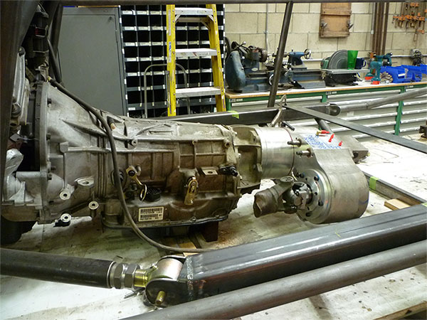
CHASSIS
After I was satisfied with the positioning of the axles, I started the chassis by laying out center lines end to end and side to side on my 48 x 120" rolling table. Then I set the engine and transmission in place and shimmed them to the correct height. I purchased a 4 speed Atlas transfer case from Advance Adapters in California and bolted it up to the transmission. At that point I could move on to the beginning stages of the chassis. I used 3x3x.1875 square tubing for the main frame rails because I liked the way I could incorporate the link mounts into them cleanly. I tacked them in place and started to add tubing as per my drawings, keeping everything square and right on with the center lines.
With lots of help from my sons cutting and tacking tubing, it didn't take long before the basic shape came to life. But as with most one-off projects, issues started to show up almost right away. I was very happy with the overall look of the car, but we were having trouble with some strength where the front and rear of the chassis transfer their load to the center section at the floor level. We solved this by making some changes to the design and reworking those areas. The chassis is made almost completely from 1-3/4" x .120 wall DOM tubing, giving me confidence in the strength of the cage.
After I completed as much as I could do on the bench, I picked the whole car up with my fork lift and moved it to some custom stands and placed the axles under the car. The stands will hold the car safely at ride height while I build the remainder of the chassis.
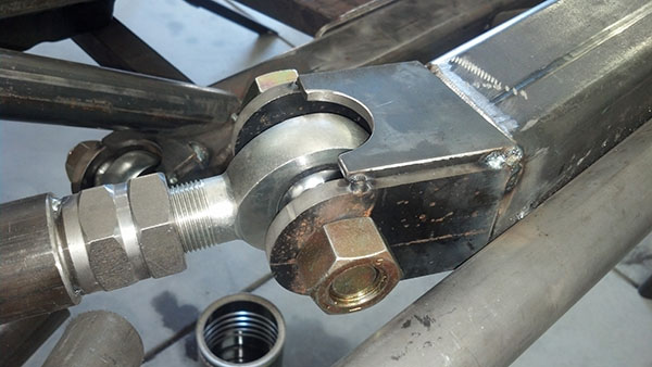
One of the issues that I was really not comfortable with was the use of the rubber-based rod ends. They only have 9/16" through holes to attach the suspension link to the axle and to the chassis. This will be a big car that will go fast. The last thing I want is for the suspension to fail at speed. So I Ebayed the joints and purchased a complete set of Chromoly 1-1/4" x 1" rod ends and stainless steel mis-alignment spacers and tacked on newly built 3/8" steel plate mounts. The links now bolt up with 1" grade 8 bolts. Much better! Now I feel great about the link system in this car.
The upper links are made from 2" x .25 wall DOM tubing and the lower links are made from 2-1/2" x .5 wall DOM tubing. I chucked the lowers up in the lathe and tapered the ends so they will slip off the rocks better and because they look cool. I built a contraption from some old skate board wheels and a small 110v motor with a speed control to rotate the links while I welded them. I also drilled (2) 1/2" holes in the tubing and plug welded the tube adapters in 2 locations.
AXLE TRUSSES AND SHOCK MOUNTS
The next project was to build the trusses for my axles. These axles don't really need trusses but they look great and give me better ways to attach all of the needed mounts. I incorporated the link mounts, sway bar link mounts, bump stop perches, and shock mounts into the design. The entire center section unbolts and lifts off the differential for service.
Then I chucked up some 1-1/2" solid round bar in the lathe and drilled and tapped the ends for my shock mounts. They run through the truss and create mounts on both sides. I water-jet some 3/8" steel for the link mounts and some 1/4" steel for the shock mount and link mount support, then tacked them in place.
This is the shock mount on the front of the front axle and the rear of the rear axle. They were water jet cut from 1/4" steel plate. The shocks use a 1/2" grade 8 bolt that threads into the 1-1/2" round mount.
It took me forever to decide on how to mount the top end of the front shocks. The problem was that in order to fit the shocks under the hood, the ride height of the car was too high. So I spent a long time reworking most of the front tubing and working in some shock hoops.
Then I just cut some holes in the hood and ta-da! Front shocks! I am using a 2-1/2"x 18" King coil over and a 2-1/2"x 18" triple by-pass on each corner. Both shocks have remote reservoirs but the coil over reservoirs are hose attached, but enough for now; I will build mounts for them later.
Watch for part 4 coming soon!